Call Us: +8613551065136

Double flanged Loose Sleeve Force Transfer Joint

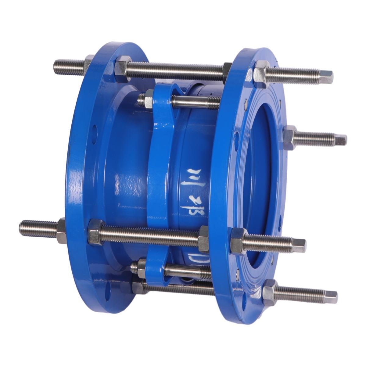
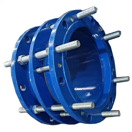
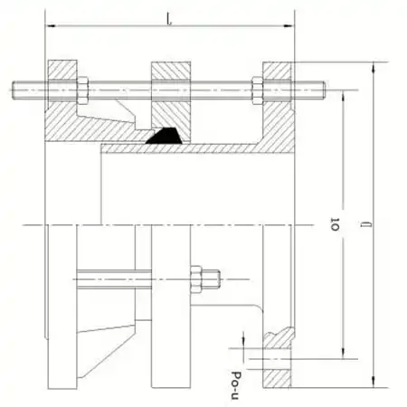
Double flanged loose sleeve force transfer joint is made by adding flanged short pipe and force transfer screw on the basis of flanged loose sleeve compensation joint.

Double flanged Loose Sleeve Force Transfer Joint

Category Tag

Double flanged loose sleeve force transfer joint is made by adding flanged short pipe and force transfer screw on the basis of flanged loose sleeve compensation joint.
Nominal Diameter DN50 – DN1200
Nominal Pressure 1.0/1.6 MPa
Applicable Temperature 0 ∼ 80oC
Applicable Medium Including sediment water, clean water, and oil products

Additional Information

Process Description

Ductile iron carbon steel is used as material to form the basic shape of the valve. The valve then goes through the process of casting, shot blasting treatment, stress-relief annealing, machining, powder coating, assembly, pressure testing, and packaging for storage. With a final inspection, the valve will be packaged and sent out.
Related Documentation
Double flanged Loose Sleeve Force Transfer Joint's
Data Sheet

Technical stuff about product.​

Double flanged loose sleeve force transfer joint is made by adding flanged short pipe and force transfer screw on the basis of flanged loose sleeve compensation joint. The compensation joint is composed of a body, a telescopic tube and a gland. This type of force transfer joint is rigidly connected and can transmit axial force once all nuts are tightened.
Features:
  1. The inner and outer sleeve can be freely extended to both ends
  2. Convenient installation of valves and pipe fittings, resulting in time and installation cost
  3. The deformation stress of pipe fittings can be eliminated
  4. Compensation for pipe deformation
  5. Eliminate the effects of earthquake, subsidence and other factors on the pipe
  6. Good sealing effect, small telescopic resistance
  7. Widely used in urban water, fire and high-rise building water supply and industrial water supply projects


Installation Dimensions Unit:mm

DN C2F

L

1.0 MPa 1.6 MPa
D D1 n-φ d D D1 n-φ d
50 / 165 125 4 – φ19 165 125 4 – φ 19
65 200 ± 20 185 145 4 – φ19 185 145 4 – φ 19
80 200 ± 20 200 160 8 – φ19 200 160 8 – φ19
100 200 ± 20 220 180 8 – φ19 220 180 8 – φ19
125 200 ± 20 250 210 8 – φ19 250 210 8 – φ19
150 200 ± 20 285 240 8 – φ23 285 240 8 – φ23
200 200 ± 20 340 295 8 – φ23 340 295 12 – φ23
250 200 ± 20 395 350 12 – φ23 405 355 12 – φ28
300 220 ± 25 445 400 12 – φ23 460 410 12 – φ28
350 220 ± 25 505 460 16 – φ23 520 470 16 – φ28
400 220 ± 25 565 515 16 – φ28 580 525 16 – φ31
450 220 ± 25 615 565 20 – φ28 640 585 20 – φ31
500 220 ± 25 670 620 20 – φ28 715 650 20 – φ34
600 240 ± 25 780 725 20 – φ31 840 770 20 – φ37
700 240 ± 25 895 840 24 – φ31 910 840 24 – φ37
800 350 ± 30 1015 950 24 – φ34 1025 950 24 – φ40
900 350 ± 30 1115 1050 28 – φ34 1125 1050 28 – φ40
1000 350 ± 30 1230 1160 28 – φ37 1255 1170 28 – φ43
1200 370 ± 30 1455 1380 32 – φ40 1485 1390 32 – φ49


Materials of Main Components

No. Part Name Material
1 Outer Cover, expansion tube, pressure plate Ductile iron carbon steel
2 Sealing ring NBR/EPDM
3 Limit screw Carbon steel galvanizing

Related products

Language

Ask For A Quick Quote

We will contact you within 1 working day, please pay attention to the email with the suffix “chuanlivalve@gmail.com”.