Call Us: +8613551065136
Double Flanged Limit Compensation Joint
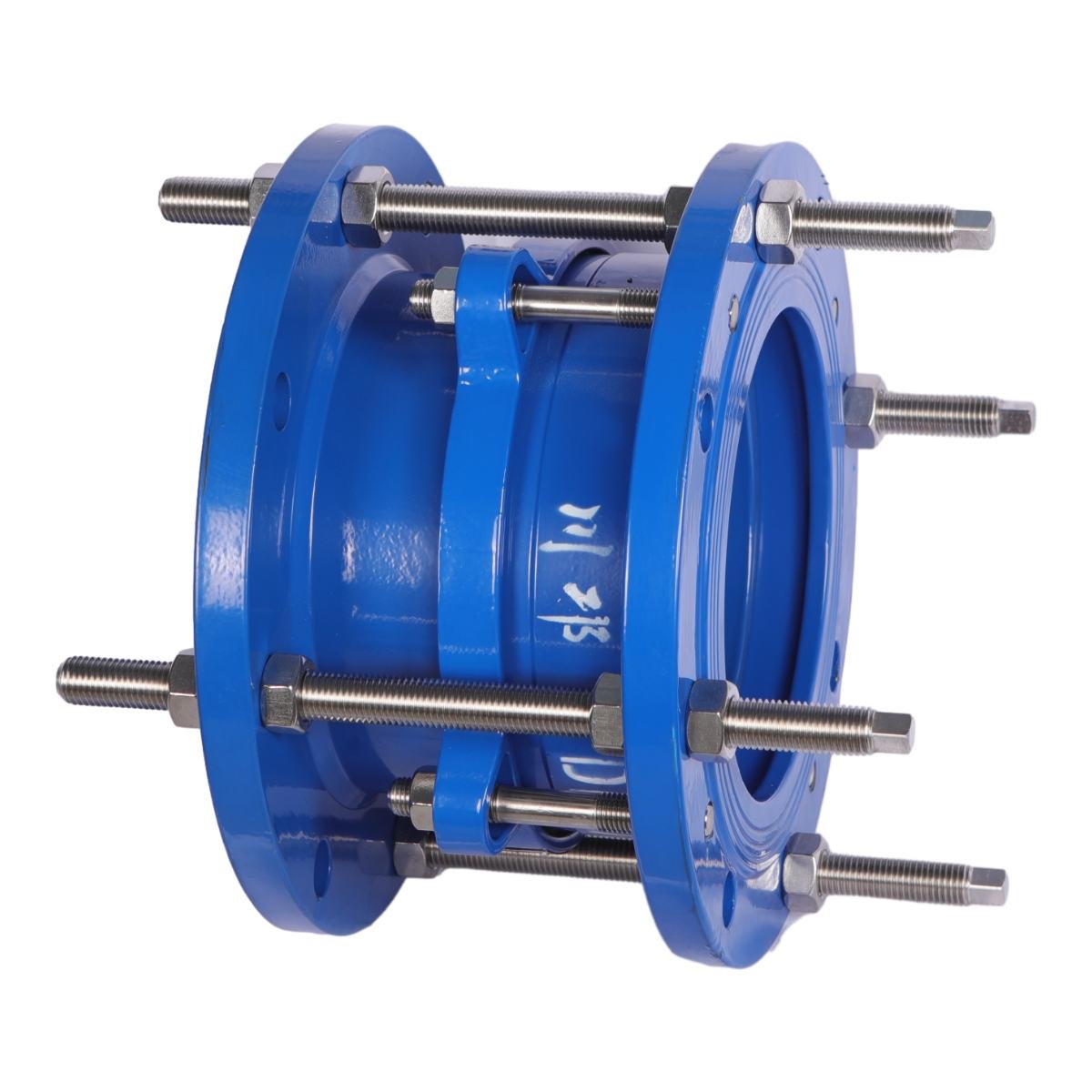
Double flanged limit compensation joint Double flange loose sleeve limit joint is composed of flange body, expansion flange, gland, limit screw, sealing ring and other parts. Once it exceeds its maximum expansion, it plays a limiting role, thus protecting valves, pumps and other equipment.


Double flange limit compensation joint Double flange loose sleeve limit joint is composed of flange body, expansion flange, gland, limit screw, sealing ring and other parts. Once it exceeds its maximum expansion, it plays a limiting role, thus protecting valves, pumps and other equipment.
Features:
- The inner and outer sleeve can be freely extended to both ends
- Convenient installation of valves and pipe fittings, resulting in time and installation cost
- The deformation stress of pipe fittings can be eliminated
- Compensation for pipe deformation
- Eliminate the effects of earthquake, subsidence and other factors on the pipe
- Good sealing effect, small telescopic resistance
- Widely used in urban water, fire and high-rise building water supply and industrial water supply projects
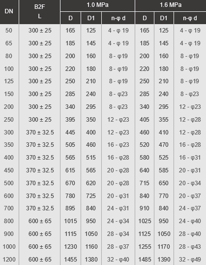
Installation Dimensions Unit:mm
| DN | B2F
L |
1.0 MPa | 1.6 MPa | ||||
| D | D1 | n- φd | D | D1 | n-φ d | ||
| 50 | 300 ± 25 | 165 | 125 | 4 – φ19 | 165 | 125 | 4 – φ19 |
| 65 | 300 ± 25 | 185 | 145 | 4 – φ19 | 185 | 145 | 4 – φ19 |
| 80 | 300 ± 25 | 200 | 160 | 8 – φ19 | 200 | 160 | 8 – φ19 |
| 100 | 300 ± 25 | 220 | 180 | 8 – φ19 | 220 | 180 | 8 – φ19 |
| 125 | 300 ± 25 | 250 | 210 | 8 – φ19 | 250 | 210 | 8 – φ19 |
| 150 | 300 ± 25 | 285 | 240 | 8 – φ23 | 285 | 240 | 8 – φ23 |
| 200 | 300 ± 25 | 340 | 295 | 8 – φ23 | 340 | 295 | 12 – φ23 |
| 250 | 300 ± 25 | 395 | 350 | 12 – φ23 | 405 | 355 | 12 – φ28 |
| 300 | 370 ± 32.5 | 445 | 400 | 12 – φ23 | 460 | 410 | 12 – φ28 |
| 350 | 370 ± 32.5 | 505 | 460 | 16 – φ23 | 520 | 470 | 16 – φ28 |
| 400 | 370 ± 32.5 | 565 | 515 | 16 – φ28 | 580 | 525 | 16 – φ31 |
| 450 | 370 ± 32.5 | 615 | 565 | 20 – φ28 | 640 | 585 | 20 – φ31 |
| 500 | 370 ± 32.5 | 670 | 620 | 20 – φ28 | 715 | 650 | 20 – φ34 |
| 600 | 370 ± 32.5 | 780 | 725 | 20 – φ31 | 840 | 770 | 20 – φ37 |
| 700 | 370 ± 32.5 | 895 | 840 | 24 – φ31 | 910 | 840 | 24 – φ37 |
| 800 | 600 ± 65 | 1015 | 950 | 24 – φ34 | 1025 | 950 | 24 – φ40 |
| 900 | 600 ± 65 | 1115 | 1050 | 28 – φ34 | 1125 | 1050 | 28 – φ40 |
| 1000 | 600 ± 65 | 1230 | 1160 | 28 – φ37 | 1255 | 1170 | 28 – φ43 |
| 1200 | 600 ± 65 | 1455 | 1380 | 32 – φ40 | 1485 | 1390 | 32 – φ49 |
Materials of Main Components
| No. | Part Name | Material |
| 1 | Outer Cover, expansion tube, pressure plate | Ductile iron carbon steel |
| 2 | Sealing ring | NBR/EPDM |
| 3 | Limit screw | Carbon steel galvanizing |